RISK ASSESSMENT ANALYSIS & SERVICES
While XOLAREN BANGLADESH offers all the safety-related services to the industries, we are also providing some exclusive services to those customers who keep ensuring top-notch safety in their workplaces. Part of that top-notch service XOLAREN is offering ARC FLASH Boundary calculation and defining it, Safety Zone marking in the facility, Selection of Personal Protective Equipment (PPE) at different type of work locations, Providing Risk Matrix in specific areas etc
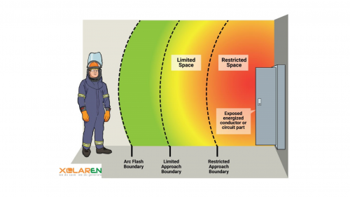
Imagine a safety bubble that envelops electrical equipment, shielding your team from harm. This is the Arc Flash Boundary. It's defined as the minimum safe working distance from energized electrical equipment at which a person could be exposed to an arc flash incident. In simpler terms, it's the line between safety and danger, ensuring that even in the event of an electrical arc flash, your team won't suffer second-degree burns.
NFPA 70E Compliance: The National Fire Protection Association (NFPA) developed NFPA 70E, the Standard for Electrical Safety in the Workplace. It outlines safety-related work practices, including arc flash safety. We adhere to this standard to the letter, ensuring that your team operates safely when working on or near electrical systems. NFPA 70B Compliance: NFPA 70B, the Recommended Practice for Electrical Equipment Maintenance, focuses on the maintenance of electrical systems. We incorporate its guidelines into our services, ensuring the reliability and longevity of your electrical equipment.
When you partner with XOLAREN, you're enlisting the expertise of seasoned engineers and consultants. Our team boasts an impressive track record in electrical system safety and optimization across various industries.
We meticulously evaluate your electrical systems, identifying potential hazards and calculating the Arc Flash Boundary as specified in NFPA 70E (Article 130.5). This knowledge forms the foundation for safer operations.
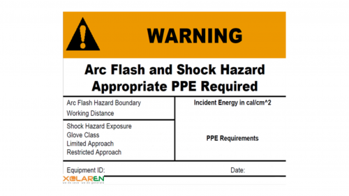
NFPA 70E has established the Arc Flash Boundary with the aim of reducing the potential for arc flash injuries among electrical workers operating near live electrical equipment. This boundary specifies the distance from the equipment at which the Incident Energy associated with an arc flash is equal to 1.2 cal/cm². It enables electrical workers to assess their risk level based on their proximity to the equipment, assisting them in establishing a safe working distance.
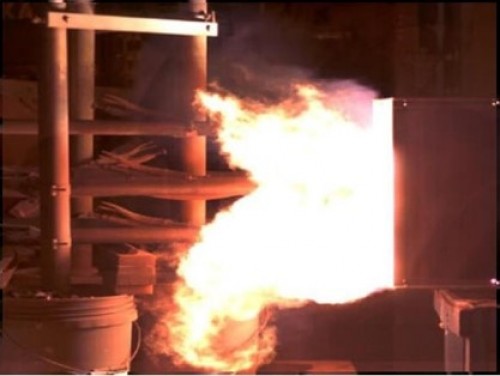
Arc flash explosions typically lead to burns, which are the most prevalent and severe injuries. These burns occur due to the intense heat generated by the arc flash. During an arc flash explosion, radiant heat emanates in all directions and diminishes in intensity as it travels farther from the point of origin. Consequently, NFPA 70E establishes an arc flash boundary distance designed to restrict the occurrence of these burns.
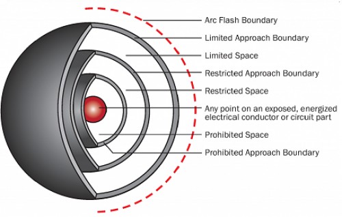
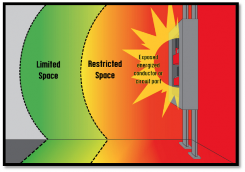
Arc Flash Boundary is the distance at which an electrical arc can flash outward, which may endanger electrical workers near electrical equipment. There are four main Arc Flash Boundaries: · Arc Flash Protection Boundary (outer boundary) · Arc Flash Limited Approach Boundary · Arc Flash Restricted Approach Boundary · Arc Flash Prohibited Approach Boundary (inner boundary)
Arc flashes represent one of the most perilous workplace hazards. They can transpire in an extremely brief time span, lack predictability, and pose a deadly threat. Consequently, it is incumbent upon all employers to ensure the proper maintenance of their systems and to be well-versed in recognizing heightened arc flash risks. This is achieved through the routine execution of an arc flash hazard analysis. This analysis encompasses multiple stages designed to pinpoint and assess the potential risks within your facility.
The initial phase involves obtaining all electrical documentation relevant to the systems under evaluation. In the case of machinery, it's essential to acquire the original documentation accompanying it. In the context of electrical systems within your facility, you should obtain the documentation furnished by the electricians responsible for the installation. This comprehensive documentation is crucial for gaining a precise understanding of the system's configuration, ensuring that no crucial details are overlooked.
Subsequently, it is necessary to cross-reference the obtained documentation with the current state of the systems being scrutinized. This step enables the identification of any alterations or enhancements that have occurred over time. If any modifications are identified, it is imperative to initiate the documentation updating process to ensure that it faithfully mirrors the current state of your systems.
Following that, the systems will undergo a short circuit study, typically carried out using software that scrutinizes the electrical pathways within the system. This study aims to determine the adequacy of protective devices like circuit breakers or fuses to manage the maximum current levels within the system. If these protective devices are found to be inadequate, they could potentially fail, leading to the occurrence of an arc flash.
A critical aspect of conducting an arc flash hazard analysis involves assessing the potential outcomes in the event of an arc flash. The engineer responsible for this analysis will calculate the potential size of the arc flash, allowing for the establishment of a designated area to be cordoned off to prevent people from entering. Individuals entering the zone at risk of an arc flash are required to wear personal protective equipment continuously.

Calculating an arc flash boundary is going to be based on the voltage of the equipment that would cause the arc flash. The exact method of calculation is different for AC and DC systems as well, so it is critical to have this information available. Many companies employ software applications that facilitate the input of voltage details for specific equipment, automatically generating the arc flash boundary calculations. This method ensures precision and yields reliable information that can be applied to establish safety distances within your facility.
If your business doesn’t have this software or wants to double-check the results manually, there are two main methods of calculating the boundary. Looking each one up will provide you with the exact calculations needed to get the distances. The options are: NFPA 70E – NFPA 70E offers a formula for calculating the incident energy of a machine. IEEE 1584 – This option uses an empirically-based formula that uses lab-tested information, and is typically seen as more accurate than the NFPA option.